2. The First Schedule to the Prevention of Pollution of the Sea (Oil) Regulations 2006 (G.N. No. S 685/2006) is amended —| (a) | by inserting, immediately after paragraph 28.8 of regulation 1, the following paragraph:“28.—9 ship delivered on or after 1 August 2010 means a ship:| 1 | for which the building contract is placed on or after 1 August 2007; or | | 2 | in the absence of a building contract, the keels of which are laid or which are at a similar stage of construction on or after 1 February 2008; or | | 3 | the delivery of which is on or after 1 August 2010; or | | 4 | which have undergone a major conversion:| 1 | for which the contract is placed after 1 August 2007; or | | 2 | in the absence of contract, the construction work of which is begun after 1 February 2008; or | | 3 | which is completed after 1 August 2010.”; |
|
|
|
| | (b) | by inserting, immediately after regulation 12, the following regulation:| 1. This regulation shall apply to all ships with an aggregate oil fuel capacity of 600 m3 and above which are delivered on or after 1 August 2010, as defined in regulation 1.28.9 of this Annex. |
| 2. The application of this regulation in determining the location of tanks used to carry oil fuel does not govern over the provisions of regulation 19 of this Annex. |
3. For the purpose of this regulation, the following definitions shall apply:| 1 | “Oil fuel” means any oil used as fuel oil in connection with the propulsion and auxiliary machinery of the ship in which such oil is carried. | | 2 | “Load line draught (dS)” is the vertical distance, in metres, from the moulded baseline at mid-length to the waterline corresponding to the summer freeboard draught to be assigned to the ship. | | 3 | “Light ship draught” is the moulded draught amidships corresponding to the lightweight. | | 4 | “Partial load line draught (dP)” is the light ship draught plus 60% of the difference between the light ship draught and the load line draught dS. The partial load line draught (dp) shall be measured in metres. | | 5 | “Waterline (dB)” is the vertical distance, in metres, from the moulded baseline at mid-length to the waterline corresponding to 30% of the depth DS. | | 6 | “Breadth (BS)” is the greatest moulded breadth of the ship, in metres, at or below the deepest load line draught (dS). | | 7 | “Breadth (BB)” is the greatest moulded breadth of the ship, in metres, at or below the waterline (dB). | | 8 | “Depth (DS)” is the moulded depth, in metres, measured at mid-length to the upper deck at side. For the purpose of the application, “upper deck” means the highest deck to which the watertight transverse bulkheads except aft peak bulkheads extend. | | 9 | “Length (L)” means 96% of the total length on a waterline at 85% of the least moulded depth measured from the top of the keel, or the length from the foreside of the stem to the axis of the rudder stock on that waterline, if that be greater. In ships designed with a rake of keel the waterline on which this length is measured shall be parallel to the designed waterline. The length (L) shall be measured in metres. | | 10 | “Breadth (B)” means the maximum breadth of the ship, in metres, measured amidships to the moulded line of the frame in a ship with a metal shell and to the outer surface of the hull in a ship with a shell of any other material. | | 11 | “Oil fuel tank” means a tank in which oil fuel is carried, but excludes those tanks which would not contain oil fuel in normal operation, such as overflow tanks. | | 12 | “Small oil fuel tank” is an oil fuel tank with a maximum individual capacity not greater than 30 m3. | | 13 | “C” is the ship’s total volume of oil fuel, including that of the small oil fuel tanks, in m3, at 98% tank filling. | | 14 | “Oil fuel capacity” means the volume of a tank in m3, at 98% filling. |
|
| 4. The provisions of this regulation shall apply to all oil fuel tanks except small oil fuel tanks, as defined in 3.12, provided that the aggregate capacity of such excluded tanks is not greater than 600 m3. |
| 5. Individual oil fuel tanks shall not have a capacity of over 2,500 m3. |
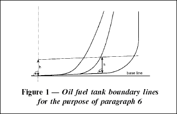
6. For ships, other than self-elevating drilling units, having an aggregate oil fuel capacity of 600 m3 and above, oil fuel tanks shall be located above the moulded line of the bottom shell plating nowhere less than the distance h as specified below:| h = 2.0 m, whichever is the lesser. |
|
|
|
| The minimum value of h = 0.76 m |
| In the turn of the bilge area and at locations without a clearly defined turn of the bilge, the oil fuel tank boundary line shall run parallel to the line of the midship flat bottom as shown in Figure 1. |
|
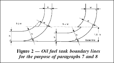
7. For ships having an aggregate oil fuel capacity of 600 m3 or more but less than 5,000 m3, oil fuel tanks shall be located inboard of the moulded line of the side shell plating, nowhere less than the distance w which, as shown in Figure 2, is measured at any cross-section at right angles to the side shell, as specified below:| The minimum value of w = 1.0 m, however for individual tanks with an oil fuel capacity of less than 500 m3 the minimum value is 0.76 m. |
|
8. For ships having an aggregate oil fuel capacity of 5,000 m3 and over, oil fuel tanks shall be located inboard of the moulded line of the side shell plating, nowhere less than the distance w which, as shown in Figure 2, is measured at any cross-section at right angles to the side shell, as specified below:| w = 2.0 m, whichever is the lesser. |
|
|
|
| The minimum value of w = 1.0 m |
|
| 9. Lines of oil fuel piping located at a distance from the ship’s bottom of less than h, as defined in paragraph 6, or from the ship’s side less than w, as defined in paragraphs 7 and 8 shall be fitted with valves or similar closing devices within or immediately adjacent to the oil fuel tank. These valves shall be capable of being brought into operation from a readily accessible enclosed space the location of which is accessible from the navigation bridge or propulsion machinery control position without traversing exposed freeboard or superstructure decks. The valves shall close in case of remote control system failure (fail in a closed position) and shall be kept closed at sea at any time when the tank contains oil fuel except that they may be opened during oil fuel transfer operations. |
| 10. Suction wells in oil fuel tanks may protrude into the double bottom below the boundary line defined by the distance h provided that such wells are as small as practicable and the distance between the well bottom and the bottom shell plating is not less than 0.5 h. |
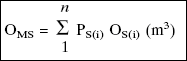
11. Alternatively to paragraphs 6 and either 7 or 8, ships shall comply with the accidental oil fuel outflow performance standard specified below:| 1 | The level of protection against oil fuel pollution in the event of collision or grounding shall be assessed on the basis of the mean oil outflow parameter as follows: | | | | | | | | | | | | | OM = mean oil outflow parameter; and |
| | | | C = total oil fuel volume. |
| |
|
| | 2 | The following general assumptions shall apply when calculating the mean oil outflow parameter:| 1 | the ship shall be assumed loaded to the partial load line draught dP without trim or heel; | | 2 | all oil fuel tanks shall be assumed loaded to 98% of their volumetric capacity; | | 3 | the nominal density of the oil fuel (pn) shall generally be taken as 1,000 kg/m3. If the density of the oil fuel is specifically restricted to a lesser value, the lesser value may be applied; and | | 4 | for the purpose of these outflow calculations, the permeability of each oil fuel tank shall be taken as 0.99, unless proven otherwise. |
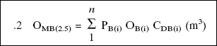
| | 3 | The following assumptions shall be used when combining the oil outflow parameters:| 1 | The mean oil outflow shall be calculated independently for side damage and for bottom damage and then combined into a non-dimensional oil outflow parameter OM, as follows:| OM = (0.4 OMS + 0.6 OMB) / C |
| OMS = mean outflow for side damage, in m3; |
| OMB = mean outflow for bottom damage, in m3; and |
| C = total oil fuel volume. |
|
|
|
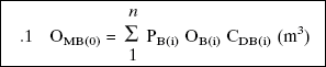
| | 2 | For bottom damage, independent calculations for mean outflow shall be done for 0 m and 2.5 m tide conditions, and then combined as follows:| OMB = 0.7 OMB(0) + 0.3 OMB(2.5) |
| OMB(0) = mean outflow for 0 m tide condition; and |
OMB(2.5) = mean outflow for minus 2.5 m tide
condition, in m3. |
|
|
|
| | 4 | The mean outflow for side damage OMS shall be calculated as follows:| i = represents each oil fuel tank under consideration; |
| n = total number of oil fuel tanks; |
| PS(i) = the probability of penetrating oil fuel tank i from side damage, calculated in accordance with paragraph 11.6 of this regulation; |
| OS(i) = the outflow, in m3, from side damage to oil fuel tank i, which is assumed equal to the total volume in oil fuel tank i at 98% filling. |
|
|
| | 5 | The mean outflow for bottom damage shall be calculated for each tidal condition as follows:| i = represents each oil fuel tank under consideration; |
| n = total number of oil fuel tanks; |
| PB(i) = the probability of penetrating oil fuel tank i from bottom damage, calculated in accordance with paragraph 11.7 of this regulation; |
| OB(i) = the outflow from oil fuel tank i, in m3, calculated in accordance with paragraph 11.5.3 of this regulation; and |
| CDB(i) = factor to account for oil capture as defined in paragraph 11.5.4. |
|
|
| | 6 | where:| i, n, PB(i) and CDB(i) = as defined in subparagraph .1 above |
| OB(i) = the outflow from oil fuel tank i, in m3, after tidal change. |
|
|
|
| | 3 | The oil outflow OB(i) for each oil fuel tank shall be calculated based on pressure balance principles, in accordance with the following assumptions:| 1 | The ship shall be assumed stranded with zero trim and heel, with the stranded draught prior to tidal change equal to the partial load line draught dP. | | 2 | The oil fuel level after damage shall be calculated as follows:| hF = {(dP + t C – Zl)(pS)}/pn |
|
|
|
| hF = the height of the oil fuel surface above Zl, in m; | | tC = the tidal change, in m. Reductions in tide shall be expressed as negative values; | | Zl = the height of the lowest point in the oil fuel tank above the baseline, in m; | | pS = density of seawater, to be taken as 1,025 kg/m3; and | | pn = nominal density of the oil fuel, as defined in 11.2.3. |
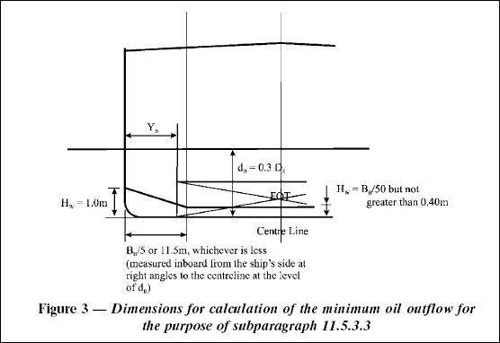
| | 3 | The oil outflow OB(i) for any tank bounding the bottom shell plating shall be taken not less than the following formula, but no more than the tank capacity: | HW = 1.0 m, when YB = 0 | | HW = BB/50 but not greater than 0.4 m, when YB is greater than BB/5 or 11.5 m, whichever is less |
| “HW” is to be measured upwards from the midship flat bottom line. In the turn of the bilge area and at locations without a clearly defined turn of the bilge, HW is to be measured from a line parallel to the midship flat bottom, as shown for distance “h” in Figure 1. |
For YB values outboard BB/5 or 11.5 m, whichever is less, HW is to be linearly interpolated. |
| YB = the minimum value of YB over the length of the oil fuel tank, where at any given location, YB is the transverse distance between the side shell at waterline dB and the tank at or below waterline dB. | | A = the maximum horizontal projected area of the oil fuel tank up to the level of HW from the bottom of the tank. |
|
| | 4 | In the case of bottom damage, a portion from the outflow from an oil fuel tank may be captured by non-oil compartments. This effect is approximated by application of the factor CDB(i) for each tank, which shall be taken as follows: | CDB(i) = 0.6 for oil fuel tanks bounded from below by non-oil compartments; | | CDB(i) = 1 otherwise. |
|
| | 6 | The probability PS of breaching a compartment from side damage shall be calculated as follows:| 1 | | | | | | | | probability the damage will extend into the longitudinal zone bounded by Xa and Xf; |
| | | | | | | | probability the damage will extend into the vertical zone bounded by Zl and Zu; |
| | | | | | | | probability the damage will extend transversely beyond the boundary defined by y; |
|
|
| | 2 | PSa, PSf, PSu and PSl shall be determined by linear interpolation from the table of probabilities for side damage provided in 11.6.3, and PSy shall be calculated from the formulas provided in 11.6.3, where: | PSa = the probability the damage will lie entirely aft of location Xa/L; | | PSf = the probability the damage will lie entirely forward of location Xf/L; | | PSl = the probability the damage will lie entirely below the tank; | | PSu = the probability the damage will lie entirely above the tank; and | | PSy = the probability the damage will lie entirely outboard of the tank. |
| Compartment boundaries Xa, Xf, Zl, Zu and y shall be developed as follows: |
| Xa = the longitudinal distance from aft terminal of L to the aft most point on the compartment being considered, in m; | | Xf = the longitudinal distance from aft terminal of L to the foremost point on the compartment being considered, in m; | | Zl = the vertical distance from the moulded baseline to the lowest point on the compartment being considered, in m. Where Zl is greater than DS, Zl shall be taken as DS; | | Zu = the vertical distance from the moulded baseline to the highest point on the compartment being considered, in m. Where Zu is greater than DS, Zu shall be taken as DS; and | | y = the minimum horizontal distance measured at right angles to the centreline between the compartment under consideration and the side shell, in m1.| 1 For symmetrical tank arrangements, damages are considered for one side of the ship only, in which case all "y" dimensions are to be measured from that side. For asymmetrical arrangements reference is made to the Explanatory Notes on matters related to the accidental oil outflow performance, adopted by the Organization by resolution MEPC.122(52). |
|
| In way of the turn of the bilge, y need not to be considered below a distance h above baseline, where h is lesser of B/10, 3 m or the top of the tank. |
| | 3 | Table of probabilities for side damage| PSy shall be calculated as follows: |
| | PSy = (24.96 – 199.6 y/BS) (y/BS) |
| | | | PSy = 0.749 + {5 – 44.4 (y/BS – 0.05)}
{(y/B S) – 0.05} |
| | | | | PSy = 0.888 + 0.56 ( y/BS – 0.1) |
| | |
|
| PSy shall not be taken greater than 1. |
|
| | 7 | The probability PB of breaching a compartment from bottom damage shall be calculated as follows:| 1 | | | | | | | | probability the damage will extend into the longitudinal zone bounded by Xa and Xf; |
| | | | | | | | probability the damage will extend into transverse zone bounded by Yp and Ys; and |
| | | | | | | | probability the damage will extend vertically above the boundary defined by z. |
|
|
| | 2 | PBa, PBf, PBp and PBs shall be determined by linear interpolation from the table of probabilities for bottom damage provided in 11.7.3. and PBz shall be calculated from the formulas provided in 11.7.3. where: | PBa = the probability the damage will lie entirely aft of location Xa/L; | | PBf = the probability the damage will lie entirely forward of location Xf/L; | | PBp = the probability the damage will lie entirely to port of the tank; | | PBs = the probability the damage will lie entirely to starboard of the tank; and | | PBz = the probability the damage will lie entirely below the tank. |
| Compartment boundaries Xa, Xf, Yp, Ys and z shall be developed as follows: |
| | Xa and Xf as defined in 11.6.2; |
| | | | | the transverse distance from the port-most point on the compartment located at or below the waterline dB, to a vertical plane located BB/2 to starboard of the ship’s centreline; |
| | | | | the transverse distance from the starboard-most point on the compartment located at or below the waterline dB, to a vertical plane located BB/2 to starboard of the ship’s centreline; and |
| | | | | the minimum value of z over the length of the compartment, where, at any given longitudinal location, z is the vertical distance from the lower point of the bottom shell at that longitudinal location to the lower point of the compartment at that longitudinal location. |
|
|
| | 3 | Table of probabilities for bottom damage| PBz shall be calculated as follows: |
| | PBz = (14.5 – 67 z/DS) (z/DS) |
| | | | | PBz = 0.78 + 1.1 {(z/D S – 0.1)} |
| | |
|
| PBz shall not be taken greater than 1. |
|
| | 8 | For the purpose of maintenance and inspection, any oil fuel tanks that do not border the outer shell plating shall be located no closer to the bottom shell plating than the minimum value of h in paragraph 6 and no closer to the side shell plating than the applicable minimum value of w in paragraph 7 or 8. |
|
| 12. In approving the design and construction of ships to be built in accordance with this regulation, Administrations shall have due regard to the general safety aspects, including the need for maintenance and inspection of wing and double bottom tanks or spaces.”; |
|
|
| | (c) | by deleting paragraph 2.2 of regulation 21 and substituting the following paragraph:| “2 | oils, other than crude oils, having either a density at 15ºC higher than 900 kg/m 3 or a kinematic viscosity at 50ºC higher than 180 mm2/s; or”; |
|
| | (d) | by inserting, immediately after paragraph 2 in Form A relating to “RECORD OF CONSTRUCTION AND EQUIPMENT FOR SHIPS OTHER THAN OIL TANKERS” under the “Supplement to the International Oil Pollution Prevention Certificate (IOPP Certificate)” in APPENDIX II, the following paragraph: | | (e) | by inserting, immediately after paragraph 2 in Form B relating to “RECORD OF CONSTRUCTION AND EQUIPMENT FOR OIL TANKERS” under the “Supplement to the International Oil Pollution Prevention Certificate (IOPP Certificate)” in APPENDIX II, the following paragraph: |
|